

Go from a sketch to a rendered scene in a matter of hours.
When I wanted to design a log home on my computer to see what it would look like under actual lighting conditions, I tried AutoCAD, 3D Studio Max and numerous off-the-shelf home design packages. None of them provided the realistic output or easy support for dealing with the log walls I desired. I had been playing with a lighting simulation package from the Lawrence Berkeley National Laboratory (LBL) known as Radiance and decided I could get what I wanted much faster by adding utilities to it.
Radiance is a physical lighting simulation system written primarily by Greg Ward Larson. It has been around since the early 1990s and recently changed licensing from a free-for-noncommercial-use license to the open-source model. The package produces great-looking images that are output in a special format that records both the texture and physical lighting of a scene, much like the professional products LightScape and VIZ 4 by Autodesk.
The packages used for movie and game making are really the graphics equivalent of junk food factories. The end result may be attractive and popular, but it isn't substantial. The physical details of lighting simply aren't as important as speed to movie and game makers, because they have a lot of pixels to push. A two-hour movie has 172,800 individual frames, and games have to run in real time. As a result, light becomes an artifact of an artistic algorithm in most graphics systems and has little basis in reality.
Radiance output is considered a lab-quality simulation of the physics of light (as long as your input is realistic) and has been rigorously tested in the professional world.
You can obtain the Radiance source code from radsite.lbl.gov. I recommend getting the source tarball, as the compiled RPMs do not include any of the auxiliary files. Once you have the tarball:
$ tar xzf rad3R4.tar.gz
$ cd ray
$ ./makeall install
Then, simply answer the questions about where you want to put the software. I use $HOME/radiance/bin for the binaries and $HOME/radiance/lib for the auxiliaries.
The makeall script doesn't install the sample scenes or the documentation, so you have to move those files to a good spot also. For example:
$ mv doc/man $HOME/radiance
$ mv obj $HOME/radiance
Be sure to add these things to the MANPATH and PATH variables in your profile. One caveat: there is an important utility called rview in the package. Unfortunately, Vim also has a utility of the same name, so use a PATH modification or rename Vim's rview. Do not rename the Radiance utility, because it is called indirectly by other Radiance utilities.
New users of Radiance first will notice the lack of an included CAD system for generating the scene description. The package was written for research purposes under UNIX in the early 1990s, and if you look at the file formats, it is obvious they were written for command-line junkies like myself who love the power of pipes and plain-text processing (my own initials are AWK, after all).
Nevertheless, there are utilities for translating geometry from formats like DXF, Wavefront and MGF so you can use any utility that will output such a format. Many of the modelers listed in the application archive of linux.org will output one of these. A Windows-based AutoCAD/Radiance module called Desktop Radiance is also available from the Radiance web site if you happen to own a compatible version of AutoCAD.
The input files of Radiance are human readable, which makes them good candidates for script generation. However, be warned: occasional terms in the documentation will cause accelerated heart rates in passing physicists, such as “watt per square meter per steradian”. Be sure to check out all the documentation on the web site. If you decide to do more than play, you might want to track down a copy of Rendering With Radiance by Greg Ward Larson, et al. It is currently out of print, so check with used book dealers.
Listing 1 is a scene that includes sky and ground, the material for brass and a sphere with the brass material applied. The sky and ground are standard. The only thing you need to edit for your own scenes are the options to gensky. The values in the listing correspond to noon on November 25 at 33° latitude north and 80° longitude west. Use negative numbers for south and east.
Listing 1. Sample Input Scene for Radiance
Each item in the scene description has the same format. The first line declares an existing material that will be applied to the entry (or void if that doesn't apply), a type name for a material or geometric primitive (like sphere, polygon, plastic or metal) and a user-defined name. The next three groups are the string, integer and real (floating point) parameters for the entry. Each of these starts with an argument count, followed by the actual arguments. They can be spread over as many lines as necessary.
Most entries have only real parameters. This explains the two zeros in the middle of most of the entries; they have no string or integer parameters. The 5 in the last line of brass indicates five real parameters, and the 4 in the last line of the sphere indicates four real parameters. The parameters are straightforward. For example, a sphere needs a center (x, y, z) and a radius.
Materials can be the hardest part of a scene. It is easiest to start by copying existing materials and modifying them to your needs. Read refman.pdf from the web site for more details.
The gensky line at the top of Listing 1 is an embedded command-line utility. Placing an exclamation point at the beginning of a line in a Radiance scene tells the system to run the line as a shell command and use the output as part of the scene. Radiance comes with a number of these utilities, and I've found that writing your own can make scene generation quick and easy.
Most of the generators put the object at the origin, which isn't likely to be the spot you wanted. The xform utility addresses this issue. Its syntax is:
xform -t transx transy transz -rx angle\
      -ry
      -s scalefactor optional_scenefile
xform can transform everything in a file, or you can pipe the output of a generator utility to it. It can scale the objects (-s factor), rotate around an axis (-ry angle means rotate around y axis) and translate to new positions (-t x y z means translate by x y z). You can use the different options multiple times, in any order. The operations are done in the order that they appear on the command line. Also, be sure to pay attention to the exact default position used by a generator. Most of them put a corner at the origin.
Figure 1 shows the effects of xform on a set of cubes generated by genbox. In this image, the viewer is on the +z axis looking back toward the origin. The red axis is +x, and green is +y.
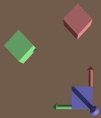
Figure 1. Behavior of xform. The axes are color-coded: +x = red, +y = green and +z = blue. The blue box was not transformed. The red box was rotated, then translated. The green box was translated, then rotated.
The blue box is the unmodified output of a call to genbox. The red box is the same genbox with an xform:
!genbox redplastic box1 .5 .5 .5 \
    | xform -rz 45 -t 2 0 0
The green box is:
!genbox greenplastic box2 .5 .5 .5 \
    | xform -t 2 0 0 -rz 45
The materials (like redplastic) were defined right before these
calls but are not shown in the listings. You can see the way the
order of parameters affects the operations and, thus, the output.
I've written a number of generators in Perl that can be used to put together log cabins and log homes (available electronically). In this article I use genlogwall, genlog and genroof. All of these output in units of inches, even though they sometimes take arguments in feet as input for convenience. The materials I use also are included in the electronic distribution.
The genlog utility generates a capped cylinder, centered along the +x axis (Figure 2). It requires several parameters:
genlog material name length_ft diam_inches
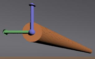
Figure 2. Unmodified output from genlog. Axes are in RGB/xyz order (R = +x, G = +y and B = +z). The x-axis is inside of the log.
The material should be predefined in your scene, and name should be something you make up. The predefined materials file I supply has three wood materials, oriented for proper-looking logs: xpine, ypine and zpine. You should choose the material that matches your eventual alignment for the log.
If you wanted to make a ten-feet tall, eight-inch diameter pole pointed in +z, with its base at (15ft, 0ft, 0ft), you'd do this:
!genlog zpine mypole 10 8 | xform -ry 90 -t 180 0 0
Remember to use the correct units for xform: 180 inches is 15 feet.
The utility genlogwall takes the following form:
genlogwall material name length_ft height_ft \
           logdiam_inches [hole_data_file]
The optional parameter is a data file that indicates what holes should be in the wall and what should be in each hole, such as a window or door. At this point, it will help if we work from the floor plan in Figure 3.
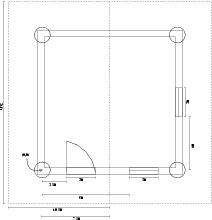
Figure 3. A floor plan for a cabin. Measurements for the holes are taken from the endpoints of the wall in which they appear.
There are four walls, each 15 feet long. I chose the southwest corner of the cabin to be (0,0,0), increasing x to the east, increasing y to the north and increasing z up. This orientation faces the building south, according to the standard-generated sky from gensky. genlogwall always places the generated wall at (0,0,0) along the x axis, as shown in Figure 4.
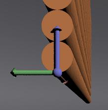
Figure 4. Nontransformed wall output from genlogwall. The axes' colors are in RGB/xyz order.
The hole data file is simple. One hole description per line:
holebottom_ft holetop_ft holestart_ft
width_ft[:w|d]
The first two numbers are measured from the floor and the latter two from the beginning edge of the wall (x = 0, x increasing). The optional tag on the end indicates that you want the wall generator to fill the hole with a window or door. Our floor plan calls for two such hole description files (see Listings 2 and 3). You can use the same data file for multiple walls, but only if you want them to have the same set of holes.
Listing 2. Hole Description File (holes/southwall.holes) for the South Wall
Listing 3. Hole Description File (holes/eastwall.holes) for the East Wall
The final touch to our cabin is the roof. Generic roof generation is tricky, so the genroof tool makes you do a bit more work than the others.
genroof generates planar pieces of roof; use it multiple times with xform to generate a whole roof.
A data file is required for genroof. In the data file, provide the x-y coordinates (in feet) of the vertexes of the piece of roof, as read from the floor plan in counterclockwise order around the edge. The vertexes all must be in the positive quadrant, and any edge of the peak must run parallel to the x axis.
To figure out the points from the plan, rotate it so the peak of the roof runs left to right. Now ignore the bottom half of the roof, and think of the lower-left corner of the top half as your new origin. Your points are then (0,0), (21,0), (21, 10.5) and back to (0,0). Not too bad.
The points should be entered one per line, separated with a space, ending with the letter b, mp or p to indicate whether the point is at the bottom, somewhere in the middle or the peak of the roof section. This is necessary because it is possible to generate odd-shaped roof sections for unusual roofs.
You also need coordinates for the end cap if you want the genroof utility to fill in the ends of the roof with logs. Looking at the floor plan in our roof orientation, you easily can see that the caps should be along the walls at (3,0)®(3,7.5) and (18,0)®(18,7.5). Add this information to the end of the roof data file prefixed with the marker c:. The completed roof data file for the cabin is shown in Listing 4.
Listing 4. The Data for Our Roof Generator (roofdata)
The command-line call for genroof is:
genroof -o overhang_ft typename name \
        roofdatafile height_ft thickness_in
The overhang parameter allows the utility to adjust the position of the piece so you can transform it to the height of the wall without worrying about meeting the slope of the roof. The completed cabin scene in Listing 5 shows the z transform for the roof pieces matches the height of the walls, even though the overhangs will droop below the top of the walls.
Our roof is symmetrical, so we use the same genroof with a different xform to make the other half. That's easy.
Radiance comes with a utility called rad that works like UNIX make. The input file to rad has a series of variables that tell it how you want to render a scene, and it figures out how to call the many other programs used to simulate the light. A commented sample is shown in Listing 6.
Most of the variables that take filenames can be defined as many times as there are files that apply. The view variable also can be defined many times. Each view definition causes the generation of a picture. You should include a name for the view, where you want to put your eyeball (-vp viewpoint), what direction you want to look (-vd view direction vector) and which way is up (-vu view up vector). I also like the -vt option for generating angular (fish-eye) views.
Using the H value with the various quality settings can take a long time (more than ten hours on 2GHz machines). Most times, the H setting is overkill, and M works fine. Use L for interactive rendering. The documentation and a little experimentation will help you figure out what is best for your scene.
To view a scene interactively, use the command:
$ rad -o x11 cabin.rif
The scene may appear bright and washed out when interactively viewing. Type e, press Enter, then click on a bright spot in the image to fix the exposure. You don't have to wait for the render to finish.
You can experiment with the exposure as much as you want. The dynamic range of Radiance image data far exceeds the dynamic range of your monitor. This means you can end up with a completely dark or completely white image that can be adjusted to your display without loss of data. This is drastically different from normal image files where adjusting the brightness too far can cause permanent loss of information.
You can load an alternate view from the rif file while interactively rendering with the L command. For example, if you have a view named interior in your rif file, typing L interior loads it. You can input a view manually by typing v and pressing Enter. Simply answer the prompts. Type q and press Enter to quit the interactive renderer.
To generate images of all of your views use:
$ rad cabin.rif
Then view the images with:
$ ximage *.picYou can adjust the exposure of an image in ximage by clicking on the image and pressing A for auto-exposure, H for human eye response or = to adjust based on the pixel you clicked.
Figures 5 and 6 show two completed daylight simulations of our cabin.
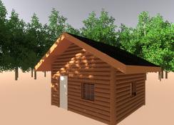
Figure 5. Perspective view of the cabin in daylight with some trees added for interest. Rendering at 3300 × 2200 for publishing quality took about five hours on a 1.7GHz laptop.
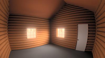
Figure 6. An angular view of the cabin interior lit only by window daylight. Rendering at 3300 × 2200 for publishing took about five hours on a 1.7GHz laptop.
You can take light readings averaged over an area from ximage. Simply drag out a box and press L for luminance or Enter for radiance values. For a quick physics tutorial of the meaning of these numbers, see www.intl-light.com/handbook/rad.html. Press Q to quit an image.
I've covered a very small part of Radiance in this article due to space limitations. If you want to further populate your scenes with the clutter of daily life, be sure to check out the links from the Radiance web site for furniture and plants.